
RF Wattmeter based on PIC16F876 and AD8307
Programming the Logic board:
There are few revisions available for this project beginning in 2002. The latest one is Ver. 1.04 from 2008 and that is what I am using too . The board use a In Circuit Serial Programming (ICSP) header , you can use any Pic programmer with ICSP header , however you have to check few things before you start .
1) disconnect all power to the board
2) remove the 10 ohm LCD back light resistor from the circuit .
The LCD takes way too much power from the VCC line and cause problems when the programmer tries to power the PIC .
You do not have to remove the resistor if you did not install the LCD panel yet.
I use the K150 programmer since it is very affordable ,it required just USB power and is easy to install . plug the following wires from the K150 ( or any ICSP Header ) to the logic board :

Select the Proper COM port , Select K150 Programmer, Select PIC16F876 Load the Hex file :
Press Program , click Verify , re-solder the resistor , you are all done !
The next thing to do is the wiring: Wiring
The next thing to do is the wiring: Wiring

Select Programmer
|

Select comm port
|

Select the PIC 16F876
|
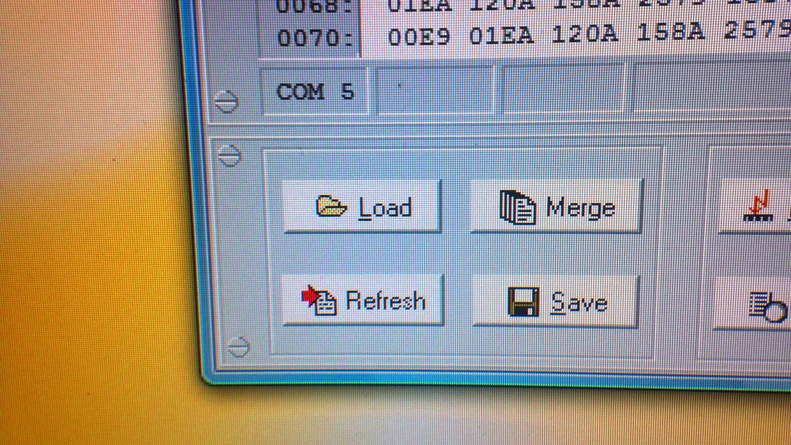
Click Load
|

Click Version M1CNK-milliwat 104 beta.Hex file
|

Click Blank, then click Erase chip
|

Click Program, watch the progress bar, when complete, Click Verify
|